Moon Clock
Geomagnetic/Auroral Activity for past 24 hours
Building an Artificial Star
With an impending telescope making project in mind, I decided that I want an easy testing option for when I grind the mirror. I wasn't interested in trying to decipher foucault shadow zones
The easiest test is a star test. A telescope with a correctly figured mirror will reflect all light from a star to a single focus. If this focus of light is cut into with a knife-edge then the illuminated telescope objective will darken instantly - a null test. Any lumpy, odd bits will remain illuminated, and are the bits that have to be polished flat,
Well that's the theory! No, wait, that's the next bit!
Artifical Star Theory
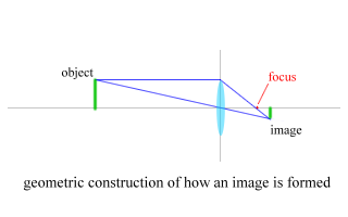
Well there are a number of ways you can make and artificial star. The classic examples given are sunlight reflecting off a spherical surface of some description - a glass marble, polished 1/4 inch ballbearing. Some people have used distant streetlights. However the design that I've settled on uses a lens and a light source. A lens will produce an image at it's focus, and if the light source is many times the focal length away and quite small, then the image of the light source formed is even smaller in size.
The reduction factor of this combination is given by the focal length of the lens / distance of the light source to the lens. In my case a 20mm microscope objective placed 550mm from the light source, the reduction factor is 20 / 550 = 0.036. Multiply this reducing factor by the size of the light source and you'll get the effective size of your "star". In my case 0.36mm.
Now its not enought to have a small light source. For ronchi testing you can probably live with whatever you get, but if you want to perform star-testing on your telescope, then the angular size of the artificial star, must be equal to or less than Dawes Limit for your telescope. Dawes limit is effectively the resolving power of your telescope. For americans the formula is 4.56 / D where D is the diameter of your objective in inches. For the rest of the world it's given by 116 / D where D is in mm. The answer is given in arc-seconds. Remember that an arc-second is 1/3600 of a degree and you'll be able to use your high-school trigernometry to do the maths and see if your star is small enough.
The other caveat around using an artificial star is with regards to how close you can place it to your telescope. Too close and you will get errors creeping in to your testing. The scuttlebutt on the internet suggests no closer than 20 times the focal length of the telescope - further away is better! The rational behind this is that a null test for a parabola (the shape we need in a telescopes mirror) needs a light souce at infinity. However any null test test where the light source is closer, really is a test for an ellipse. The question is how close can we get away with having the light source (our artificial star) before the difference between an ellipsoid and a paraboloid starts to matter?
The definitive artical by Richard Berry in Sky and Telescope used the filament of a light bulb as the actual light source. However now we have access to super-bright LEDs, which is what I have opted for. I also chose one that mostly emitted light in the 540nm band, the optimum wavelength for visual viewing, but there is no reason why you could not use any other colour.
You will need:
- battery clip and battery
- switch
- superbright LED
- resistor
- Something to hold it all together. I used PVC pipe, but you could make a box/tube from wood or cardboard, or whatever :-)
The circuit is basically an LED in series with a resistor connected to a switch and battery. I decided that Iwas going to use a terminal block to connect the components together as my soldering skills are a bit naff. (If necessary, it makes it easier to change and experiment with resistor strength)
I also chose to mount the LED on home-made binding posts. These are simply brass screws with a 1mm hole drilled in each end. The wire ends of the LED are bent into two "feet" and these are pushed through the holes, and clamped in place by a screw. Allows me to easily replace and change the LED should I want to.
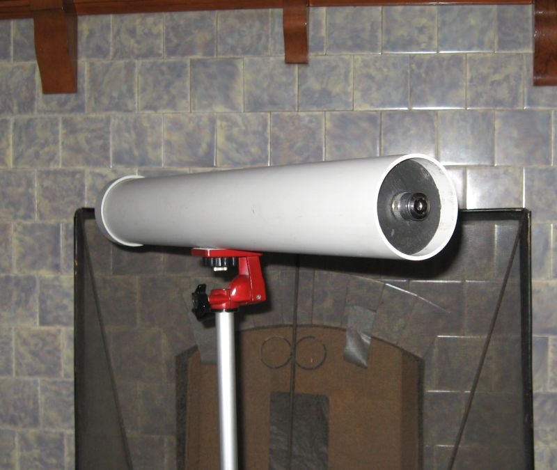
This picture shows the completed artifical star. The endcap contains the LED and power source and the front end has the microscope objective.
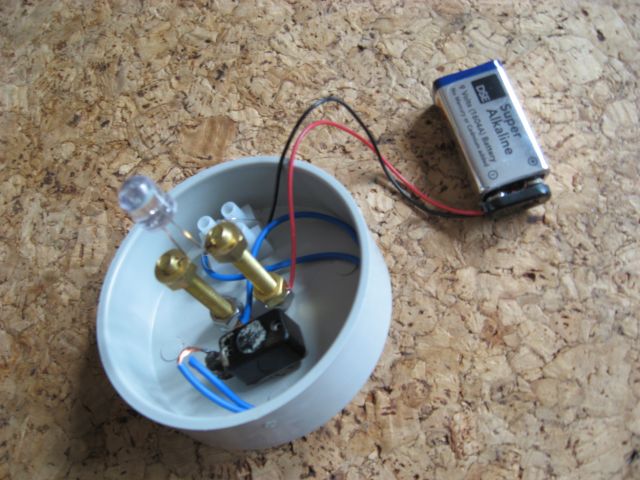
Here is the view of the endcap. the high intensity LED is mounted on two brass binding posts made from screws. In series with this is a resisitor of 300 ohms (This was from the datasheet that came with the LED for use with a 9v battery, other LEDs will have different requirements, I think the usual minimum is 100 ohm.) This is necessary as you'll burn out your LED. Because I was lazy and didn't want to try and solder I used a terminal block connector to join the battery, resistor and switch together.
Bibliography
Sky & Telescope November 1992 - contains the article by Richard Berry that talks about his experiments with using and making artificial stars.
http://observatory.mvastro.org/library/Star_Test/ArtStar.html - another version.