Moon Clock
Geomagnetic/Auroral Activity for past 24 hours
Building a simple aurora detector
This device is called a magnetometer. It shows changes in the Earth's magnetic field. The very first users of the magnetic compass were aware that magnetic north did not point to true north, and that the compass needle sometimes trembled and shifted for no apparent reason. Eventually a connection was made between this and the appearance of the aurora and by the 19th Century people were beginning to understand the further connection between the Earth's magnetic field, the aurora, and activity on the Sun.
Although modern magnetometers are sophisticated electronic devices, anyone can make this version with hand tools. You wont need to buy anything exotic part from a cheap laser pointer and maybe a neodymium magnet. By utilising the simplest optical and mechanical principles you will be able to make a device that is exquisitely sensitive.
Suspension Magnetometer or Declinometer
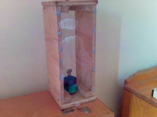 Early version made from plywood and plastic sheet
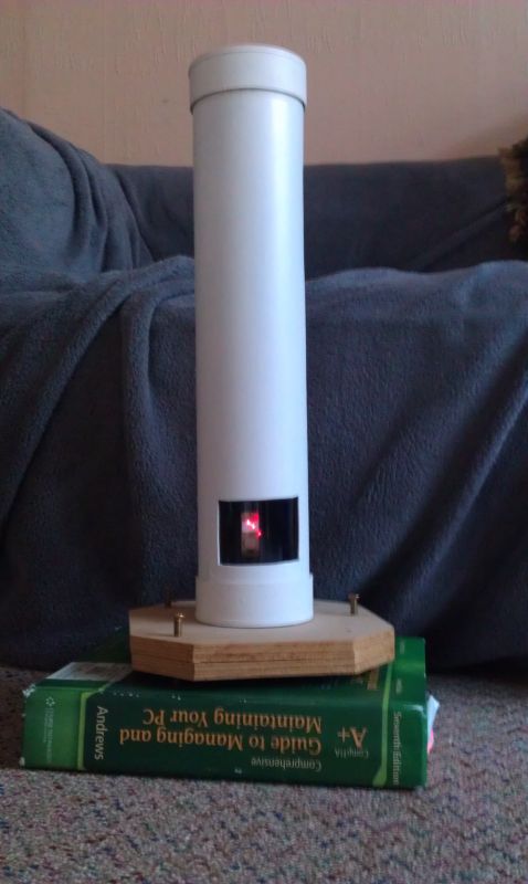 Current version made from PVC pipe, with adjustable feet.
This device is one of the easiest to make. It was popularised in Sky and Telescope magazine as a "jamjar" or "Sodapop bottle" magnetometer. Go back a whiles and this simple device had another name: a declinometer. During the 18th and 19th centuries, people were aware of the deviation of magnetic north from true north. This was called magnetic declination and devices like this were used to measure it.
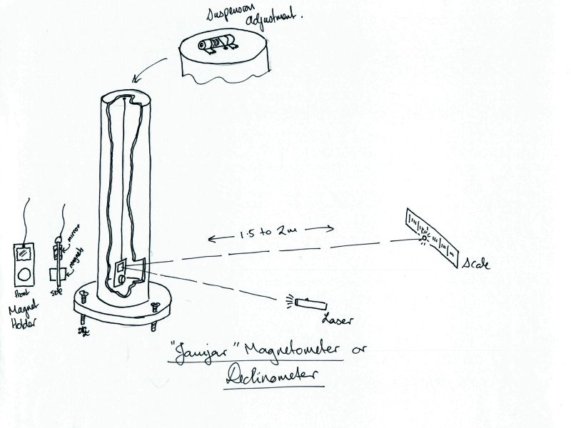
As you can see from the diagram, it's nothing more than a magnet suspended from a thread. Attached to the magnet is a mirror. We will use a laser pointer to bounce a dot of light off this mirror, onto the wall. We will use a simple scale to determine movement of the laser pointer dot. By having a longer distance between the scale and the mirror, we can amplify the tiny movements of the magnet.
This device can be as simple or complicated as you wish to make it. Some things to keep in mind:
- The magnet should be enclosed inside something, so that air currents do not disturb it. PVC pipe works well. You CANNOT use any steel screws, bolts, washers etc in it's construction (Some brass woodscrews are actually brass-coated steel, so be careful here). You will want to make a small window for the laser pointer to shine through. You can try using perspex, actual glass, mylar or even a single taut layer of sandwich wrap/cling film. You may find the laser pointer reflection becomes slightly distorted, so you will have to experiment.
- The scale can be a ruler, a piece of graph paper pinned to the wall, etc...
- Make the suspension filament or thread as long as you can (Try not to go shorter than 300mm if you can). Short lengths of thread are relatively stiff compared to a longer length, and may offer a measurable resistance to the magnet movement. Of course, for what we want to do, this may not matter.
In the above design the thread runs from the magnet holder through a tiny hole in the roof of the housing and is wrapped around a stick. This can be taped in place once you have the length of thread right.
- Make the suspension thread as THIN as you can. This will offset the stiffness of the fibre affecting how the magnet lines up. Very fine sewing thread would probably be ok. I've used "invisible" thread which is just ultrafine monifilament line. I've untwisted polyester twine and split it into finer and finer strands to good effect. For the finest filament, you can unbraid cheap polyester rope. As you do this you realise that the braided strands are themselves comprised of numerous fine strands of nylon filament, the thickness of spider silk. You'll need keen eyes, good task-lighting and a clean surface. This is probably the best modern analogue to "cocoon silk" mentioned in old texts on scientific instruments.
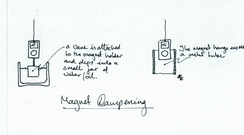
- You will want to dampen the oscillation of the magnet as quickly as you can. Some ideas include a small tail that comes off the magnet holder and dangles in a small jar of oil or water. A tidier solution is to hang the magnet just inside a non-ferrous metal tube/pipe (eg: aluminium, brass or copper). Eddy currents will provide natural braking for the magnet preventing it from endlessly oscillating
- A distance of about 1.5m to 2m from the magnetometer to the measuring scale will provide plenty of sensitivity. Longer distances will make it even more sensitive, but also a little fussier to adjust, more prone to pick up vibration, etc.
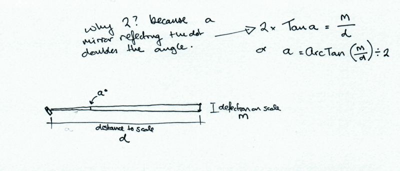
If you want to measure the changing angle of the magnet in degrees, you can use some high-school trigonometry:
 Some links to sites that have nice implementations are:
- Make Magazine's article
- An example that is computerised, but the basic magnetometer is simple enough
- This is a good simple implementation.
What will it show
Once you have everything set up, what can you see? For most people that live in an urban setting, cars passing in the street will show as small momentary drifts. For my setup at home with a scale distance of 2.8m, the pointer drifts about 2mm. Modern cars have a lot less steel in them now, so they're not so bad. I can occasionally detect large trucks coming down the motorway about 90m from my house. The magnetometer will show any changes in it's environment, including the movement of steel and magnetic objects near it, so try and position it as best you can to minimise this.
While the pointer is generally steady, a disturbed geomagnetic environment shows up as small, constant trembling in the pointer. These might only be 1-2mm or so, but to me they are an indicator to keep an eye on things.
What about aurorae? If you are monitoring your magnetometer every 15-20mins or so you may see sudden "large" changes in position. If you eliminate the possibility of any local cause, then you have probably witnessed a massive change in the Earth's magnetic field.
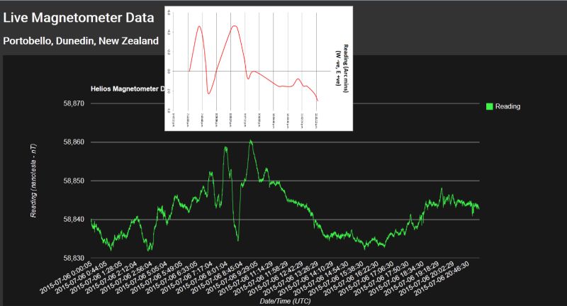
Below is a hand-plotted chart of the declinometer, photoshopped against data from a professional-quality magnetometer at DunedinAurora.nz at the time of a small scale aurora.
 With thanks to DunedinAurora.nz
You can see that when the professional instrument was showing clear fluctuations in magnetic field strength, the home made declinometer was showing obvious swings east and west. The declinometer quietens down at approximately the same time as the magnetometer.
This was a small storm, so the total deflections were in the order of 6mm either side of the zero mark. They were more subtle and took place over the course of an evening. More powerful geomagnetic storms can easily cause pointer shifts of up to 20mm @ 2.8m scale distance. The storm that hit on St Patrick's Day 2015 caused the pointer to visibly shift over 50mm in minutes.
A Selected Bibliography.
- Laboratory instruments : their design and application. by Elliott, Arthur, London : Chapman & Hall, 1959. 2nd ed
- A manual and handbook originally published in the 1930s that goes into good depth about the construction and theory of analogue instruments. This was found in the stack of the local library.
- Magnetic Compasses and Magnetometers, Hine, Alfred, London: Adam Hilger Ltd , 1968.
- The best, most in depth book that I have come across that deals with the mechanical specifics and mathematics of mechanical compass and magnetometer construction. Full explanation of the design and use of the Kew Magnetometer. Includes chapter on inductor instruments (ie: flux gate compasses and magnetometers.) Many line drawings and references to papers on construction and design. Reads very much like Sidgewick's Amateur Astronomers Handbook. This book is must read.
- Title
- definition